'iomixer' basic overview

The system consists of a hardware board and a web browser based configurator. The hardware board connects to a computer via USB for setup. Since the web browser cannot directly access serial ports, a 'relay server' must be started which runs in the background and allows the web browser and hardware board to communicate.

The term 'server' just means a program that waits for and replies to network connections, the user does not interact with the relay server other than to start and stop it. It needs to be a native application (not a web page) to access serial ports, and is the only part of the system that cares about OS type.

I have built and tested the relay server for Linux, Windows, Mac and RaspberryPi so you can use whichever of those you prefer. Since the user interface runs in a browser, which I have tested with Chrome, Firefox, Opera and Edge. For the most part it seems to work in Safari too, but I have not checked that so much and it would be a lower priority.

Why make a 'relay server' instead of using Web Serial

The current iteration of the hardware is a board like this, about 54mm square:


There are 40 I/Os, of which 37 are broken out into configurable pins (two are dedicated I2C and one is just an SMD LED). Most of the pins are arranged with a GND and 5V for convenience (red headers). The yellow headers are 3.3v for convenience with analog inputs (eg. potentiometer). There are 3 onboard addressable RGB LEDs and some female pin headers shaped to match the layout of nRF24L01 and common mini-display headers.

Input


Output


Here 'up to' means that using a pin for one purpose means it becomes unavailable for other purposes. Many features require specific pins, eg. UART, rotary encoder, duty PWM, analog input. Some features also require more than one pin, eg. using a UART requires two pins, some SPI displays use 5 pins.

Power

The board can be powered by micro USB or by 5 - 15V applied to the red headers. If more than 5V is applied to the red headers, the solder bridge for the onboard RGB LEDs should be disconnected.

GPS inputs

Currently only μ-blox UBX protocol input is supported. The required configuration of the GPS module can be done automatically, and optionally saved so that no configuration is needed next time. These modules have been tested: M8N, M8P, 7M, 6M, BN452/M9N, BN880, BN220, BN180.

External I2C device addresses

The onboard IMU uses the default I2C address for MPU6050. In order to use a second IMU, it will need to have its address pin jumpered so that the I2C addresses do not clash, and each IMU node in the configuration will need to specify which IMU should be used. The same applies for I2C barometers and compasses.

nRF24l01

The 32 bytes of the nRF24 packet can be arranged as any combination of floating point number (4 bytes) or single byte. If every byte was used as a channel this could be considered a 32 channel radio, although each channel would have somewhat coarse resolution (256 distinct values).

Since packets are delivered as bit-perfect digital data, numbers requiring high precision (eg. lat/lon coordinates) can be safely transferred. In theory a 2 position switch is only one bit of information so each byte could contain 8 on/off switch values - but this is an unlikely requirement and is not implemented at this time.

Addressable RGB LED strings

Up to 128 addressable LEDs can be used in one string. To use the 3 onboard LEDs a solder bridge can be used to power them, with no more than 5V applied to the red headers.

Display screens

The outputs referred to as 'display' are various small screens, some pictured below. The easiest ones to use will be those with a pin ordering that matches the headers, ie for I2C: (GND VCC SCL SDA) and for SPI: (GND VCC CLK MOSI RES DC CS). Currently the supported drivers/screens are:

The displays can only show text, always 8 pixels per line, one line per 'display' node. The value can be prefixed with a label and given some basic formatting such as maximum decimal places. These lines of text are updated at 50Hz, one line per loop taking turns. So for example if you have 5 lines as in the photo below, each line will be updated at 10Hz.


MIDI

To use the MIDI nodes, a device with MIDI in/out ports is required. It is common for modern MIDI equipment to have only MIDI over USB which is not supported.

Serial bus servos

The protocol for serial bus servos is the LewanSoul / HiWonder system, as used by the cheap and popular LX-16A robot servo and many others. The configurator can be used to set the id for each servo.

EEPROM

Although there is no actual EEPROM, 'store' nodes can be used to save values in a section of the SPI flash to be preserved across power cycles. Values for up to 1000 nodes can be saved.

Compass calibration

Compass calibration is a pain in the ass. A pre-made node configuration can be used to collect readings as the compass is rotated, while the onboard LEDs flash to indicate when new values are found that expand the known range for each axis. As more of the magnetic range is explored the LEDs will flash less, giving immediate visual feedback about whether your movements are actually doing something productive. By seeking out the orientations that cause flashing, calibration can be done more efficiently and the realtime feedback makes you feel like slightly less of a fool while you're dancing around.

The 'heading' property of the compass node uses sensor fusion with an IMU for tilt compensation. This requires the compass and IMU to be fixed in the same frame, and the correct axes selected for compensation.

Load cell calibration

Load cell calibration requires measuring two separate loads and specifying the real-world measurement between them (eg. grams, ounces). These settings are part of the load cell node properties and actually pretty easy to set up.

Gamepad emulation

The default USB device enumeration when plugged into a computer is a STM32 Virtual Com Port, for communication with the relay server. This can be changed to become a composite USB device for simultaneous use as a gamepad and VCP. On Linux this requires no extra setup, and on Windows the device can be manually specified as composite device pretty easily.

On MacOS composite device detection seems to be rather problematic so a third option is available, to become purely a gamepad. This works well as a gamepad but takes away the ability to communicate with the relay server. To revert back to the default USB device type requires connecting pin 40 to 3.3V on startup, to ignore the saved configuration and start with a blank configuration.

gcode-style text interaction

Using a UART connection, node values can be set and read by an external system using text commands. The format is somewhat similar to gcode:

Firmware updating

To update the firmware, an option is selected in the configurator before power cycling the board. This will restart the board in bootloader mode. A second power cycle will revert to normal. While in bootloader mode new firmware can be flashed, also via the browser configurator.


Pin allocation priority of features

Some features have more restrictions on which pins they are able to use. For example any pin can be a digital input or output, but an nRF24L01 or SPI display must use specific SPI pins. To ensure that less flexible features are catered to first, there is a 'pecking order' to decide which features have priority for pin usage. In the list below, features higher in the list can make pins unavailable for those below them.
  1. nRF24
  2. UART
  3. Rotary encoder
  4. PPM input
  5. Analog input
  6. Servo PWM input
  7. Digital input

  8. RGB LED output
  9. Display output
  10. Duty cycle PWM output
  11. PPM output
  12. Servo PWM output
  13. Digital output

The features panel lists features in their priority order, along with the current pin allocation status. In the image on the left, servo PWM input requires specific pins and therefore has priority over digital input. Pins 9 and 10 are shown in green to indicate they are good to go for servo PWM. Likewise the digital input using pin 8 has no conflict, also green.

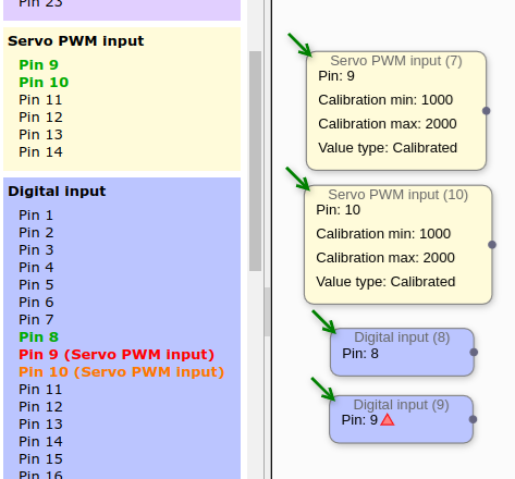
Pin 9 has also been selected for use as a digital input but conflicts with a higher priority feature, so is shown in red along with the name of the other feature it conflicts with.

There are no conflicts for pin 10, but since it has already been allocated by a higher priority feature, is shown in orange as a reminder/warning in every feature where it will not be available.


Configuration examples

The inputs and outputs are connected to each other by setting up connections between 'nodes'. Here are some simple examples.

Direct channel 2 of SBUS input to a servo on pin 14, with custom endpoints and midpoint:


Direct a servo signal from pin 13 to pin 37 at a limited rate of change (3 seconds for full travel, eg for flap movement):


Display the temperature according to barometer on a mini display screen:


Mix channels 1 and 2 of PPM input at 50% each and output to a servo on pin 14:


Make the first 3 LEDs green when GPS has more than 3 satellites, otherwise make them red:


Pulse LEDs 1-8 between red and blue every 2 seconds:


Augment a pilot command with IMU value (gyro stabilizer):


This example would require two separate devices, both with a GPS and nRF24 module connected. The upper section outlined in blue is a transmitter, which sends its lat/lon over the nRF24 radio. The lower section would be a receiver which compares that lat/lon with its own location and sets digital pin 16 high when the two locations are greater than 150 meters apart.


Hopefully that gives a rough idea. This network of nodes is upated at 50Hz.


While connected by USB, the execution can be paused/resumed, stepped through one iteration at a time, and the value of each node can be viewed in real time, like this:


While connected by USB, 'tweak' nodes can be used to adjust values in real time. That is, the value is reflected on the device immediately as the user twiddles with it in the configurator. This is particularly useful for color adjustment and control surface adjustment:


The configuration is stored on the device in a separate flash memory, not as compiled code in the memory of the microcontroller itself. This means the configuration can be 'pulled' from the device back to the configurator for further work or if the original setup is not ready to hand (or was deleted by accident etc). The pulled configuration is not 100% complete (eg. node names are not included) but is fully functional.

The size of the configuration is limited by the RAM size of the microcontroller, and the time taken to process one loop of the configuration. The usage can be checked after uploading to the device, shown as 'memory size' and 'looptime' in this screenshot. With the current hardware the limits are about 20,000 for each (bytes or microseconds). Incidentally the numbers shown here are for the foamboard car lights demo, which I think ended up as the largest config I've made so far:


The relay server auto-detects when a device is connected or disconnected, and available devices are shown in the configurator. Typically the relay server will be running on the same computer as the configurator, but since it's a server, they could also be on different computers. If the relay server was made available to the wider internet, the configurator could connect from anywhere.

That's probably enough of an information overload for now. I put the configuration interface here if you want to have a look (first-time page load may be slow):
https://iomixer.com/configurator

This is just as I have been working on it with no consideration for anyone else yet. So it's a bit messy, there is zero documentation and there's nothing you can actually do with it unless you have the hardware device, but might be interesting to look around a bit.
Nodes are connected by dragging from an input nub (little white circle) to the source node, and can be disconnected by clicking on the nub. You can also connect in the opposite direction (from the source to the destination) by holding ctrl and dragging from anywhere on the source node to anywhere on the destination node. This will connect to the first unused nub, if you want a different nub you can drag to the specific nub you want. Nodes with a green arrow coming in are external (hardware) sources and can have no inputs, vice versa for nodes with a blue arrow going out.

The content of each side panel can be changed with the 'view' option pulldown. To add nodes choose the 'Nodes' view and click on the node type you want. New nodes will be added at the current center of the view. There is no undo/redo yet. Right now the only way to save a configuration is to click 'Export' in the export panel and copy+paste the JSON from the textarea into a file. Clicking 'Import' will wipe the current configuration and replace it with the contents of the textarea. By default there is a simple config (aircraft strobe lights) in the export panel area when the page is loaded, so you can click 'Import' to quickly have something to play with.

Experiments playlist

I'm keeping a playlist here for all my videos that are related to this project, mainly proof of concepts for features as I add them:
https://www.youtube.com/playlist?list=PLzidsatoEzeieb0l_EUxpR0p7ed_RUPD6